Anatomy of a Wind Turbine
By Kate Bachman | August 1, 2010
Category: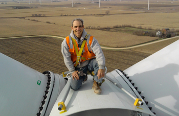 Utility-grade turbines can be constructed of as many as 22 major component groups and 8,000 subcomponents, creating a multitude of manufacturing opportunities. Here, ironworker John Hammack installs components for Blattner Energy on a NextEra Energy wind turbine.
A vast array of manufacturing processes are needed to produce commercially available wind turbine equipment. The manufacturing operations needed to produce the subcomponents—which can number up to 8,000—for a turbine include metal fabricating, machining, casting, forging, electronics, heat treating, painting, and grinding.
Design and build quality is critical, because most utility-grade and community-grade wind turbines have an expected operating lifespan of more than 20 years. The average utility-grade wind turbine is subject to an operating environment 10 to 20 times more hostile than the average U.S. automobile’s throughout its life, as reported by the National Renewable Energy Laboratory. Temperature, elevation, and wind conditions all play a role in determining a turbine’s effective service life.
Commercial wind turbines generally are classified in three size ranges:
- Small Wind turbines generally are defined as having a capacity output of less than 100 kilowatts (kW). These units comprise 30 to 80 parts; provide 120/240, single- or three-phase AC or DC output; and are used on a home, farm or small business.
- Community Wind turbines typically have output ratings of between 100 kW and 1,000 kW (1 megawatt, MW), provide 600-V, three-phase output; and comprise between 1,000 and 3,000 parts.
- Utility-grade wind turbines are generally classified as those with output capacities of 1 MW and larger. They provide three-phase output and are designed to feed into a transmission grid that services a distant load center. Utility-grade wind turbines are installed 300 feet in the air, with the nacelles consuming a 60- by 14- by 13-ft.-sq.-ft. area. These turbines have as many as 22 major component groups and 8,000 subcomponents.
A wind turbine has four major sections—the tower, hub, blades, and the machine head, or nacelle (see Figure 1).
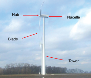 Figure 1Each of the four major wind turbine sections—tower, hub, blades, and nacelle—must withstand tremendous temperature and wind conditions. During operation, blades tip speeds commonly exceed 160 miles per hour.
Within the utility-grade wind energy sector, manufacturing opportunities are generally categorized as small, large, and A—critical.
The small category is composed of components such as simple sheet metal guarding and bracketry that are commonly made in most manufacturing facilities. This type of work generally has few code requirements, is constructed of carbon steel, and generally is open-toleranced.
Large sector components typically include large bracketry, custom crane structurals, towers, and some nacelle-supporting structurals. Again, generally they are made of carbon steel. In some rare cases, aluminum and stainless steels are also used. Most components in this sector must adhere to American Welding Society (AWS) D1.1- or D1.2-type welding requirements and are subject to non-destructive testing (NDT)—both in-process and upon completion.
The third sector, commonly known as A, includes the largest and most critical components. Examples are main rear frames, front frames (when they are not cast configurations) and generator frames. These can vary in size up to 10- by 8- by 16 sq. ft., with weights up to 20,000 lbs. Items in this sector typically have significant quality specifications that require coordinate measuring machine inspection and NDT—both in-process and upon completion—using methods such as dye pen, magnetic particle, and ultrasonic.
Nacelle
Most turbines currently being installed in North America are one of two distinctly different designs—conventional gear-driven and direct-drive permanent-magnet (PM).
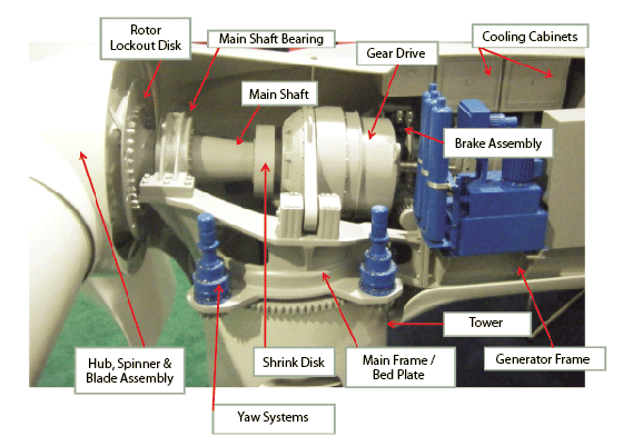
Gear-driven Nacelle. This type is the most common. These nacelles can be as large as 150 U.S. tons.
Some of the manufacturing operations needed to produce the 8,000 subcomponents for this unit are metal fabricating, machining, casting, and forging (see Figure 2).
Both the main frame and the generator frame are commonly fabricated, but some designs call for them to be cast.
- Rotor Lockout Disk—casting, machining
- Main Shaft—forging, machining
- Shrink Disk— forging, machining
- Brake Assembly—casting, machining
- Cooling Cabinet—fabrication
- Guards and Structural Framework—fabrication
- Generator Frame—Metal fabrication, ductile iron casting, machining
- Main Frame /Bed Plate—Metal fabrication, ductile iron casting, machining
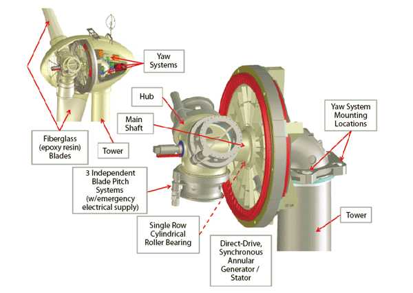
Direct-drive PM Turbine Machine Head/Nacelle. In a direct-drive configuration, the rotor hub assembly directly drives the generator without the need for a gear train arrangement. This design can reduce nacelle weight and size. However, direct-drive configurations can place additional demands on the initial design phases, as the changes in nacelle weight distribution often exhibit unique dynamic loading characteristics requiring special consideration (see Figure 3).
- Main Shaft—forging, machining
- Hub—casting. machining
Some direct-drive PM designs incorporate low-speed, synchronous generators with no direct-grid coupling. Output voltage and frequency vary with the speed and are converted for output to the grid via a DC link and an inverter achieving high-speed variability.
Castings are used more extensively than fabrications, as a result of specific design considerations in direct-drive PM turbines.
Towers
Within the utility-grade wind sector, a tower is shipped to the installation site in lengths of approximately 50 ft. These sections are constructed by assembling 10-ft.-wide sections together, usually using automated welding.
Tower coatings generally are zinc-based followed by both epoxy and urethane topcoats for increased UV resistance.
A finished tower section ready for assembly commonly weighs more than 40 tons. The tower often accounts for 10 percent of the total turbine cost.
Towers typically have unique specifications that they must adhere to, including specialized inspection and manufacturing practices (see “Sugar beet equipment manufacturer finds sweet success making wind towers,” published in the Jan./Feb. issue, Green Manufacturer, p. 25). Tower coating processes and materials are commonly governed by process-specific criteria such as ISO 12944.
Blades
Blades are constructed of composites of wood, fiberglass, resin, and carbon. These structures can have as many as 102 layers of material in the root ends and as few as two at the tips. As is the case with most wind components, design and build quality of blades is critical because tip speeds commonly exceed 160 miles per hour during operation.
Turbine OEMs
Utility-grade wind turbine OEMs currently operating in North America include General Electric (Florida, South Carolina), Gamesa (Pennsylvania), Clipper Windpower (Iowa), Acciona (Iowa), DeWind (South Carolina), and Nordic Windpower (Idaho). Several OEMs have plants under construction: Nordex (Arkansas), Siemens (Kansas), and Vestas (Colorado). Site selection teams for several other European and Asian wind turbine manufacturers are at work across North America, evaluating wind farm locations and supply chain resources as part of their decision process.
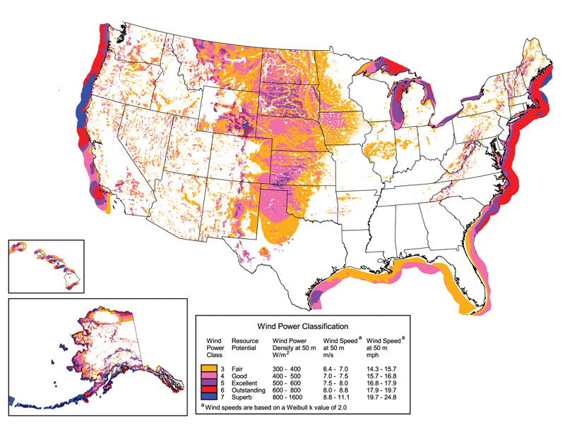
Location. Most utility-grade wind turbine OEMs have selected locations in proximity to North America’s best wind resources (see Figure 4). Wind industry Tier 1s, such as blade and tower facilities, subsequently have sited themselves in the same wind corridors to increase logistics efficiency.
The utility-grade wind energy industry has not been immune to the negative economic climate. Supply chain activity is down as OEMs prepare themselves for the projected increases in activity in late 2010 and 2011.
In light of this, now is the time to investigate market opportunities so as to be better equipped to reap the benefits that utility-grade wind energy manufacturing has to offer.
Get additional information by attending one of the many supply chain events being held in North America by organizations such as The Great Lakes Wind Network, American Wind Energy Association (AWEA) and the FMA Communications Green Manufacturer Network.

Side by side, we move metal fabrication forward.
FMA unites thousands of metal fabrication and manufacturing professionals around a common purpose: to shape the future of our industry, and in turn shape the world.
Learn More About FMA


